
01 / Structural performance
Know how your design carries the load.
Understand where a component deforms, which load paths matter, and when a simplifying assumption stops being useful. We turn your structural question into a focused finite element analysis.

Will it hold up under the conditions that matter?
A useful FEA study starts with the load case, the material and the decision you need to make. We establish how a part is supported, how an assembly transfers forces, and which operating conditions must be represented. Model detail follows the engineering question.
Stiffness, strength & stability
Evaluate displacement and stress under defined loads. Investigate buckling sensitivity and compare changes in section, material or geometry.
Nonlinear behavior & contact
Represent changing contact conditions, large deformation and nonlinear material response when a linear model cannot describe the problem.
Dynamics & fatigue
Study natural frequencies, forced response and time-dependent loads. Assess fatigue using suitable load histories, material data and an agreed evaluation method.
Thermal-mechanical response
Translate temperature fields into thermal expansion and stress. Account for temperature-dependent behavior where it affects the design.
Simulation, made visible
Explore the behavior.
Images and animations from the UNIKE Europe portfolio. Animations play automatically as they come into view. Use the controls to pause or replay.
Linear structural response
See the connection between geometry, deformation and the way a structure carries load.
Frame deformation
The blue frame moves against a pink reference shape, making the deformation pattern visible through the animation.
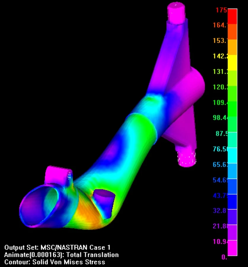
Stress in a structural connection
A finite element contour highlights how the response varies across the connection and its transitions.

From assembly to component
An aircraft-engine illustration connects the overall assembly with detailed structural models.
Nonlinear mechanics in motion
Contact, forming and cutting examples show why changing geometry and material behavior can matter.
Contact & large deformation
Crossed tools interact with a meshed block. The block changes shape as the contact conditions evolve.
Forming under contact
A workpiece deforms between surrounding tools. The changing contour field follows its response during the forming sequence.
Material cutting
A cutting tool advances through a meshed workpiece, with a contour field showing the evolving local response.
Dynamic loads & thermal effects
Different operating conditions call for different models and carefully defined inputs.
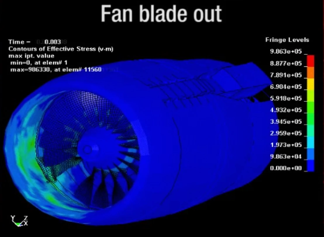
A transient event
A fan-blade-out illustration shows a structural contour during a rapidly changing load event.
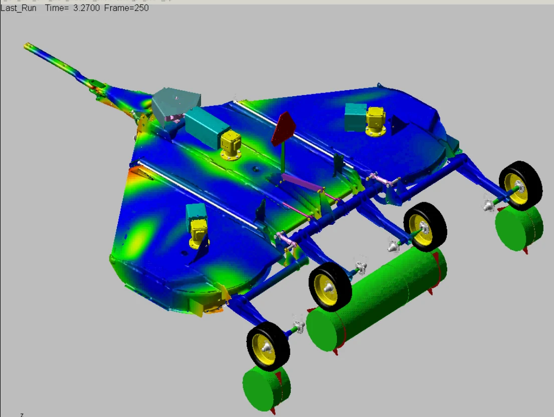
Loads over an operating cycle
A flexible assembly illustrates the link between system loading and the structural response used to define a fatigue assessment.
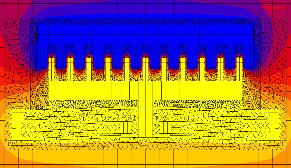
Temperature through an assembly
A meshed thermal model shows how the temperature field varies across the assembly and its surroundings.
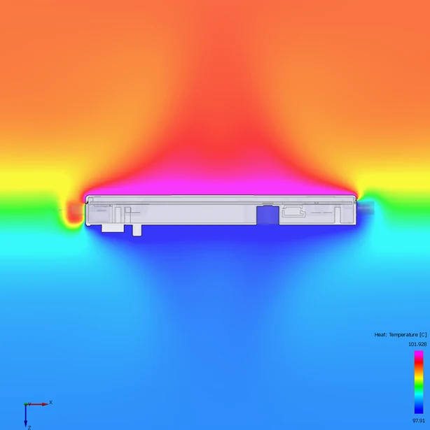
Heat transfer to the surroundings
A temperature-field illustration makes the heated region around a component visible.
Explore the design
Use simulation to examine a design and frame the next engineering question.
Design exploration
A bracket-model animation from the European design-optimization examples. Objectives and manufacturing constraints are defined for each application.
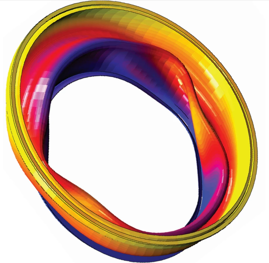
Response around a ring
A structural contour shows the response around an annular component and its features.
Illustrative media from UNIKE Europe. Original software labels, legends and attributions are retained. These examples describe European portfolio material.
From analysis to action
What you take forward.
- A documented model with loads, constraints and assumptions
- Results that identify critical regions and relevant response quantities
- A comparison of design options and the limits of the assessment
A useful starting point
Geometry, material properties, assembly interfaces, operating loads and any available test data. We agree on the scope before building the model.
We agree on methods, deliverables and the level of validation for your application.
Need realistic loads from a moving system? Explore multibody dynamics.Start with the engineering question
What do you need to understand?
Tell us about the component, the system, or the decision ahead.