
02 / Motion & system behavior
Understand how your system moves.
Mechanisms do more than move. Joints, drives, contact and structural flexibility determine how loads develop. Multibody dynamics connects that behavior to the decisions you make in design.
What happens when everything moves together?
We examine motion and force transmission across the mechanism, including transient events and interactions between components. A model can start with rigid bodies and develop to include flexible parts or control-system behavior where the question requires it.
Kinematics & motion
Investigate trajectories, available travel and the relationship between input motion and system response. Compare mechanism configurations early.
Forces & load histories
Determine joint reactions, drive loads and component forces across an operating cycle. Use relevant time histories to inform structural assessment.
Contact & flexible bodies
Study the effect of impact, changing contact and component compliance. Include structural flexibility when it changes forces or motion.
Mechanics & controls
Investigate interactions between mechanical behavior and control inputs. Define the required coupling and the available control model before implementation.
Simulation, made visible
Explore the behavior.
Images and animations from the UNIKE Europe portfolio. Animations play automatically as they come into view. Use the controls to pause or replay.
Mechanisms in motion
Follow the movement, then examine the interactions and response of the connected components.
Motion over an obstacle
A tracked vehicle crosses a gap. The sequence shows how the chassis, wheels and track respond to the changing terrain contact.
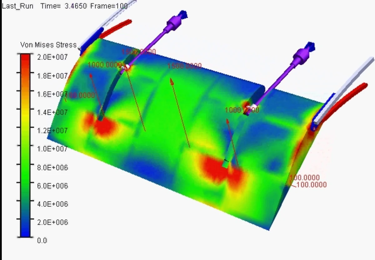
Flexible-body response
A plate-and-linkage model combines joint motion with a stress contour on the flexible structure.
Look inside the system
Link the mechanism model to motion definitions and time-dependent results.
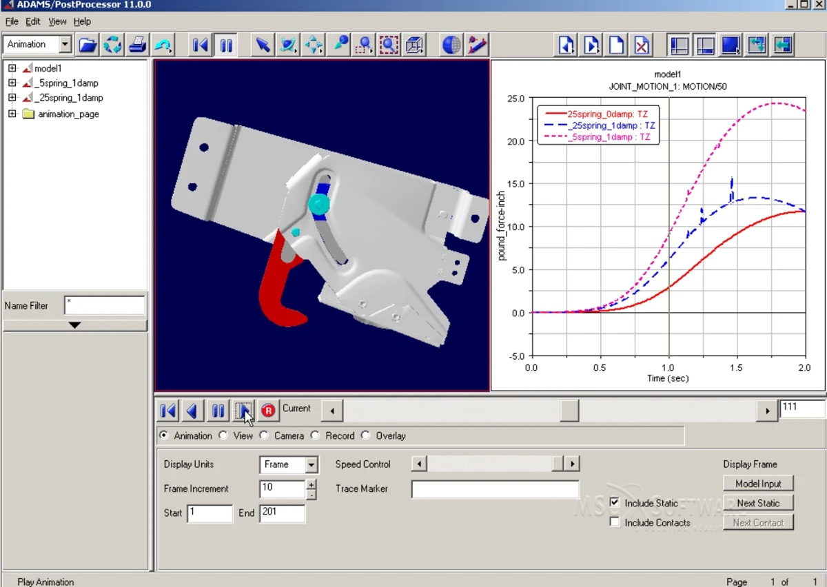
Model, motion & time histories
A mechanism model is shown alongside response curves, connecting movement with quantities evaluated over time.
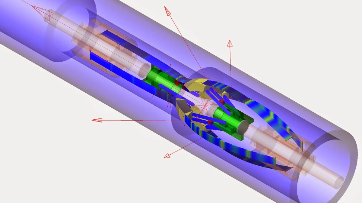
Inside a moving assembly
A cutaway view reveals the components, connections and motion definitions inside an assembled mechanism.
Illustrative media from UNIKE Europe. Original software labels, legends and attributions are retained. These examples describe European portfolio material.
From analysis to action
What you take forward.
- Motion histories and an explanation of system behavior
- Joint reactions, contact forces and critical operating events
- Load cases or time histories for subsequent component analysis
A useful starting point
Mechanism geometry, masses and inertia, joint definitions, drive inputs, contact assumptions and representative operating cycles.
We agree on methods, deliverables and the level of validation for your application.
Follow the loads into your components with structural analysis.Start with the engineering question
What do you need to understand?
Tell us about the component, the system, or the decision ahead.